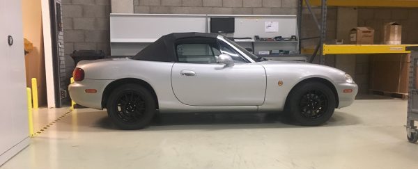
As you could read in my previous post, I’ve worked on the coupe roof from my basement during corona. In the meantime, I’ve also worked on my car. First of all, to fix the terrible seat position in the mx5. Second of all, to change the steering wheel position.
Fixing the steering wheel position.
Let’s start with the easy part. Fixing the steering wheel position. As I really like to sit low, and close to the steering wheel, I wanted to change it. Because even though I am a small guy (1.75m), I was still sitting way too far from the steering wheel. It felt like I was sitting in a lorry.
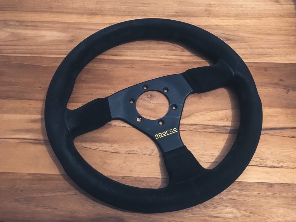
Luckily, the steering wheel position was fixed quickly with a 330mm sparco steering wheel and a 50mm spacer.
Let’s fix the seat position.
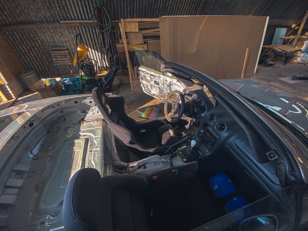
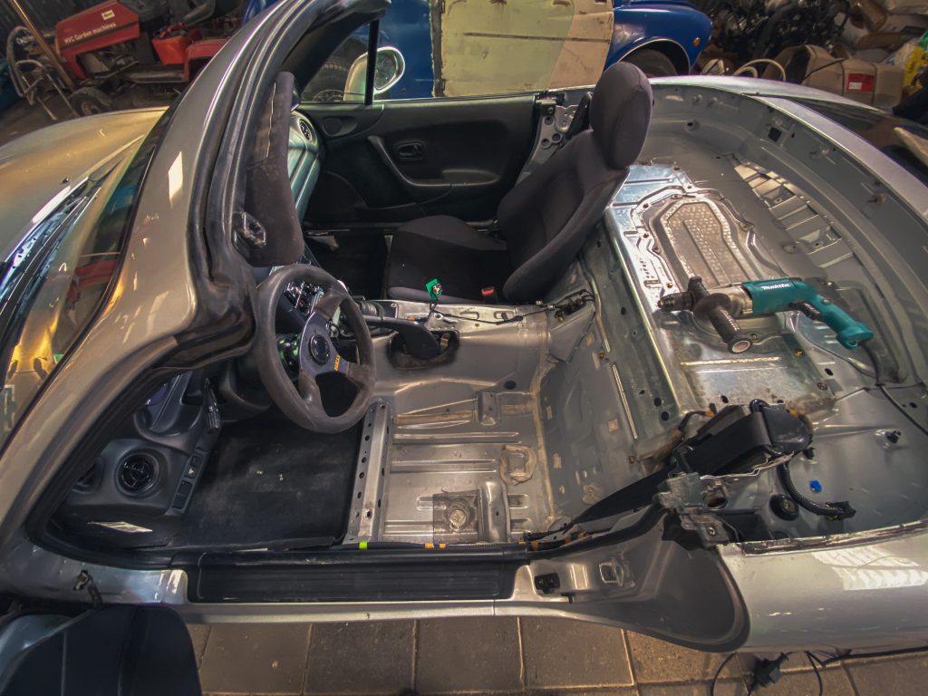
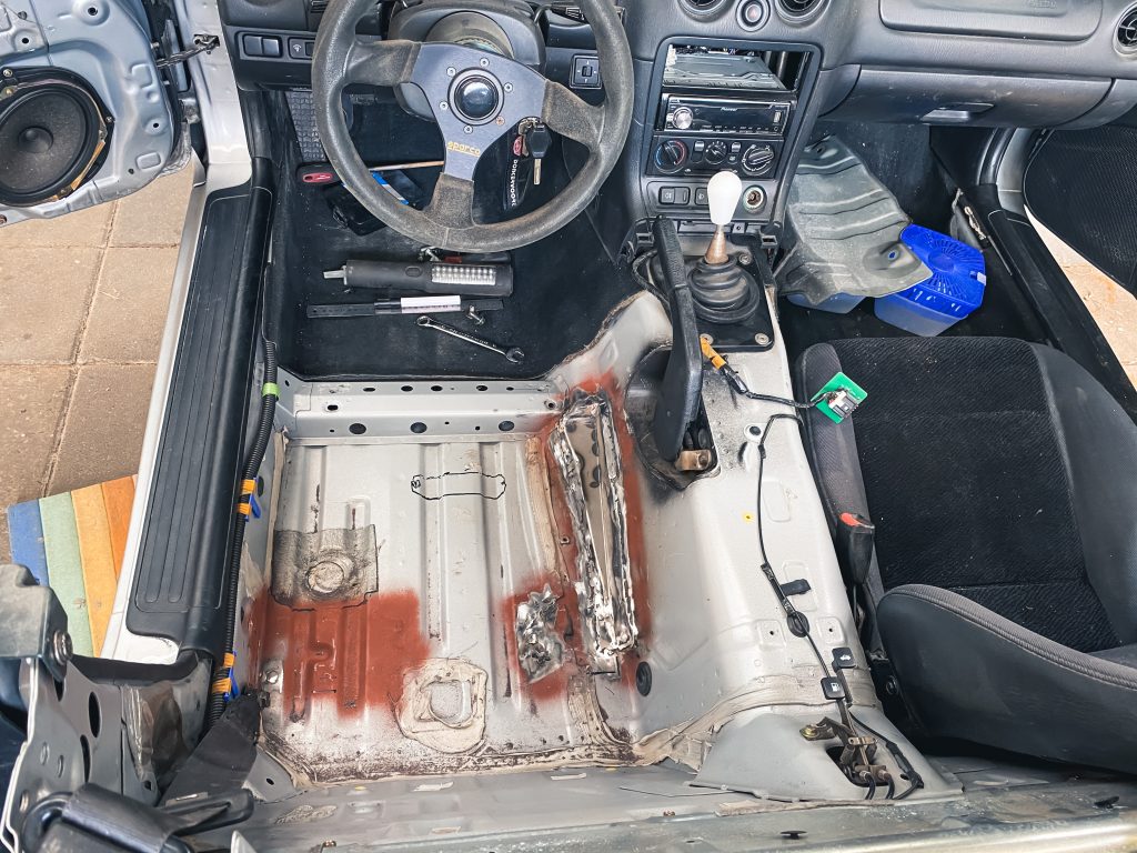
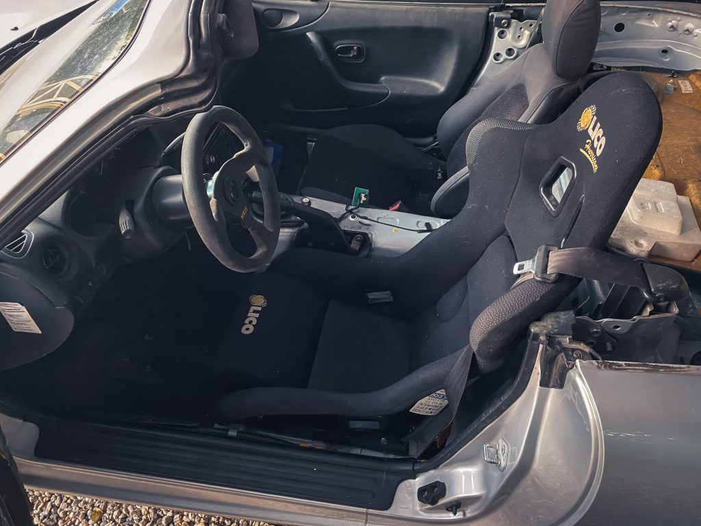
Now, it was time to sort out the seat position. First of all, I removed the original seat and placed a bucket seat loosely on the floor. I quickly came to the conclusion that I wanted to sit as low as possible, straight on the floor. This seating position felt right immediately. But….. there were some challenges. The original mounting points were getting in the way. And sitting in the middle of the steering wheel would mean: cutting a hole in the tunnel. On the upside, I thought I could re-use the original front mounting holes.
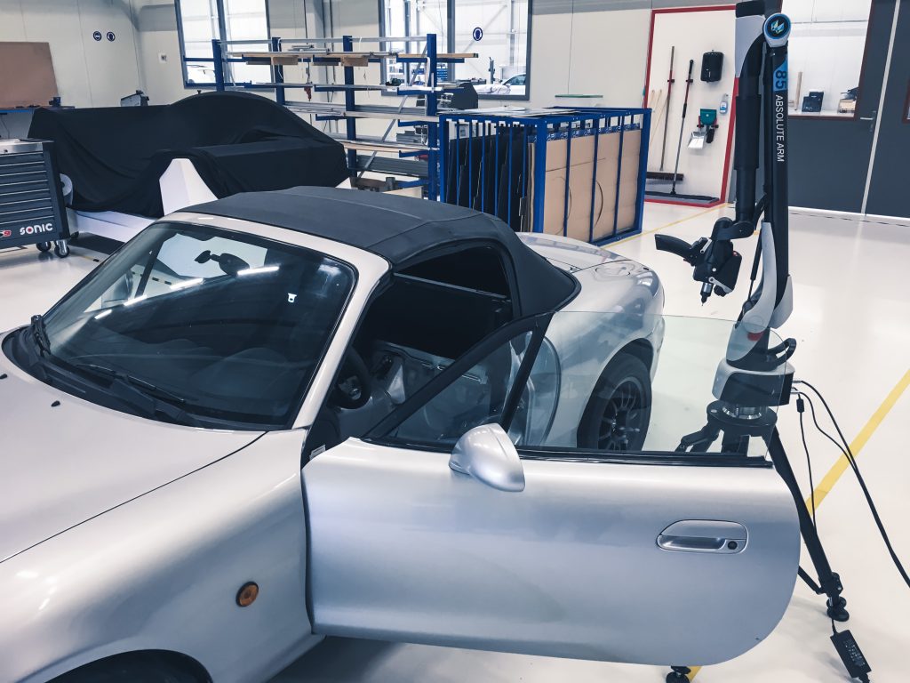
Why not use a 3D scanner?
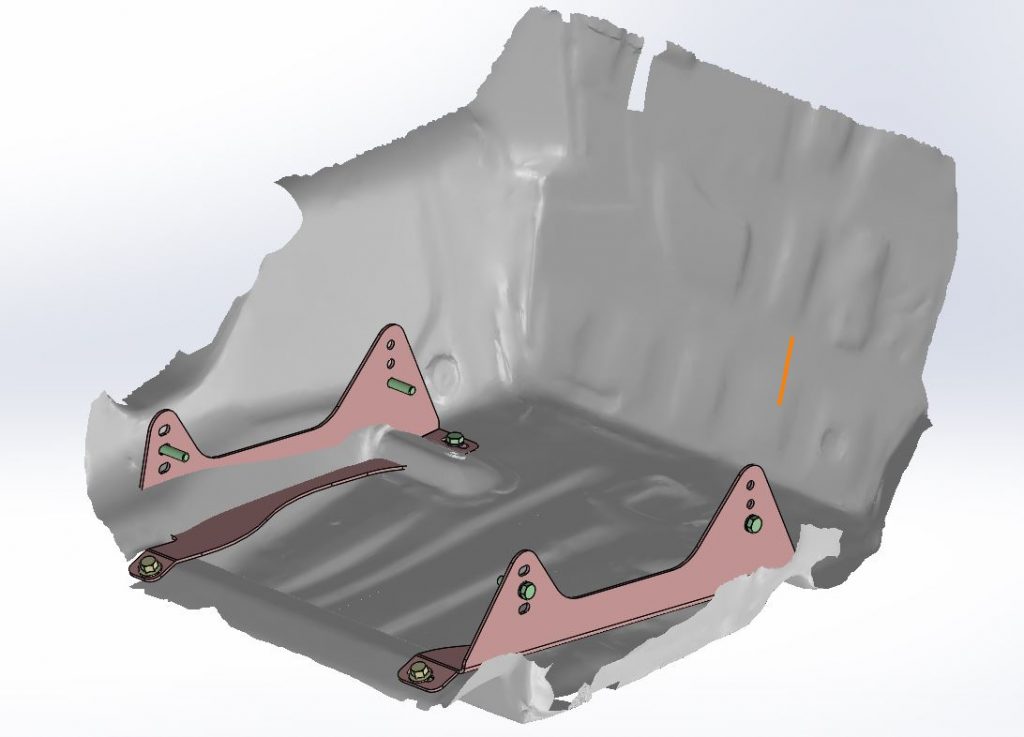
At the time we had a fancy 3D scanner at work, so… why not use this heavily expensive piece of equipment and design the brackets from scratch? Another advantage is that it’s easy to move things around in a CAD. I could easily check what needed to happen to sit on the floor and in the middle of the steering wheel.
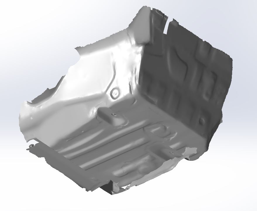
X, Y, Z directions.
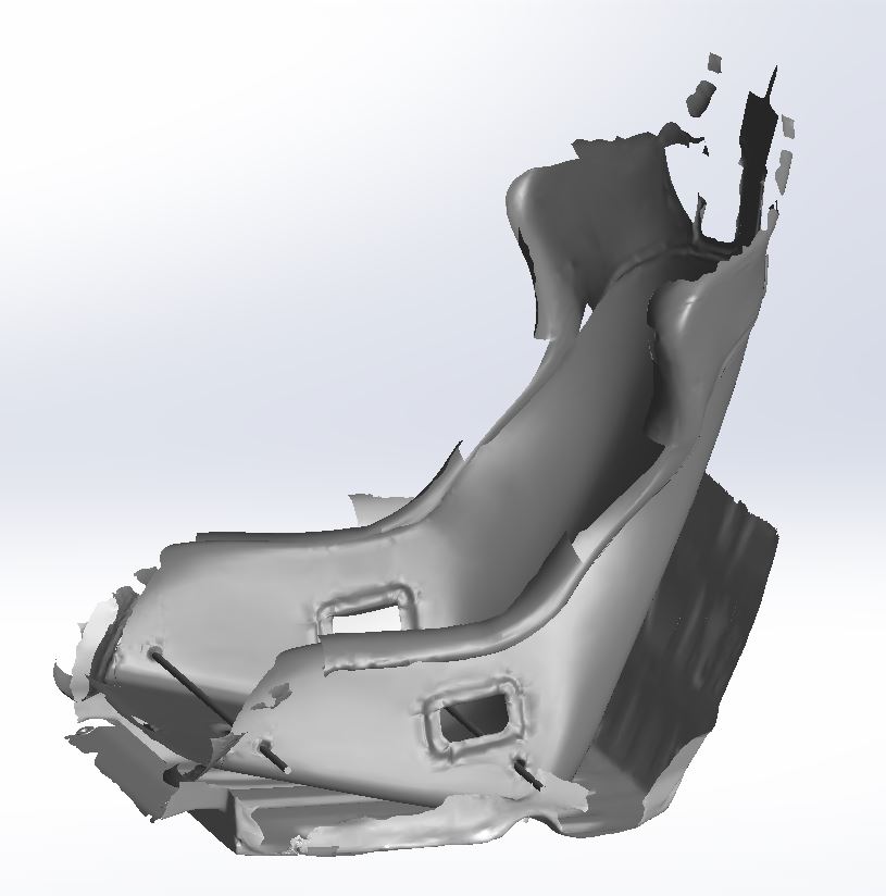
After the 3D scan, I converted the raw .stl files to surfaces to use the scan data with Solidworks. To find the center, I scanned a piece of the steering wheel to align the XZ-plane. (X-axis is the direction the car drives, Z-axis is percudicular to the ground and the Y-axis is percundicular to the X-axis). I also found the center of the seat.
Together with the 2D drawings supplied by sparco via the internet, I made two solid bars which represented the mounting holes of the seat. The seat was now fixed in Y-direction. Fixing the seat in Z-direction was also easily solved, I just constrained it to the floor of the car.
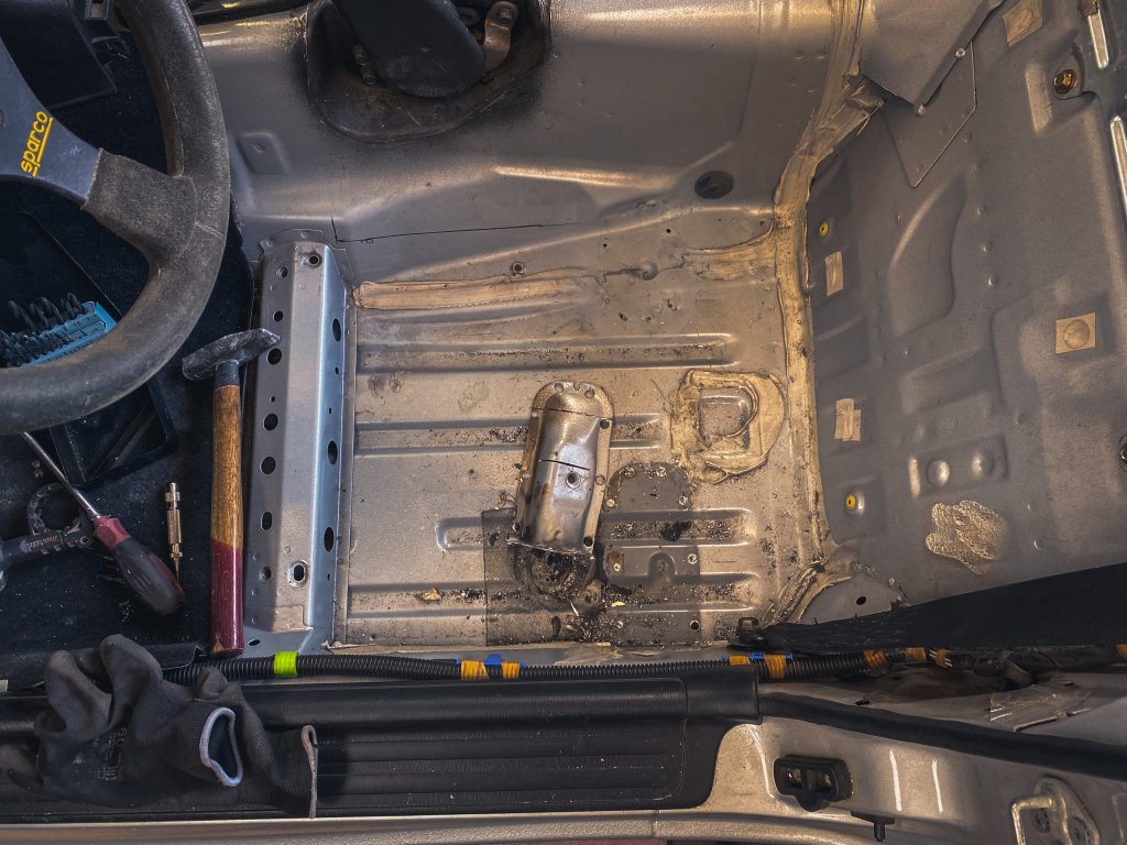
To fully constrain the seat position in CAD, I needed to know the X-direction and the angle of the seat. Therefore, I drilled out the spot welds in the car of the original mounting points in the rear. This way, I could place the seat on the floor. I positioned the seat to my liking and measured the angle + position in X-direction.
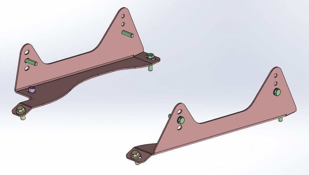
Designing the seat brackets.
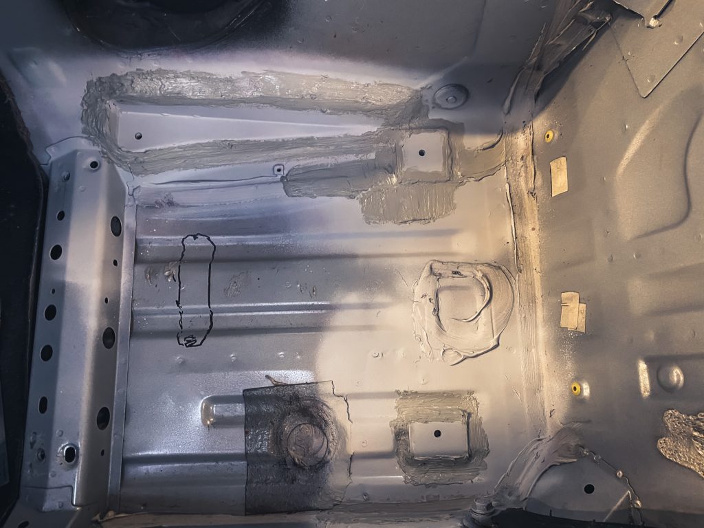
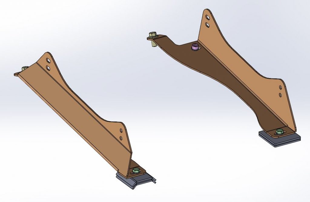
As all the boundaries were defined, I designed two seat brackets via the FIA regulations. As you can see, I needed to cut out a part of the tunnel. This is visualised in CAD and to my opinion the hole was not big at all. I cut a piece of steel and shaped it to fit the hole, also I added a third mounting hole there. This way, the mounting is in line with the mounting of the seat. The original mounting hole will be re-used. The main purpose of the original hole for the right bracket will be the alignment of both brackets.
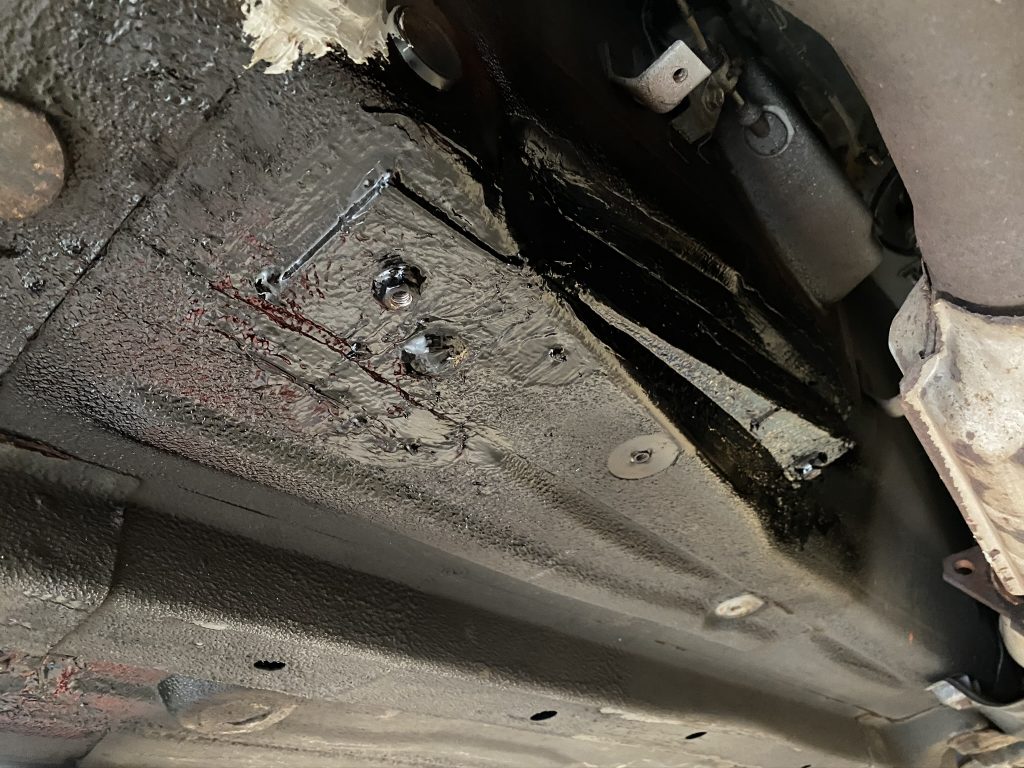
The original floor became a sandwich with 3mm counter plates – on both sides for the rear mounting points. The third hole in the right bracket also got a counterplate of 3mm underneath. All plates were welded to the original floor, following the FIA regulations.
Thanks to my friend.
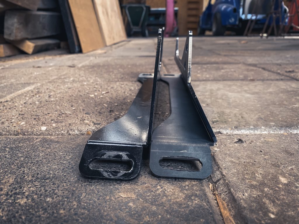
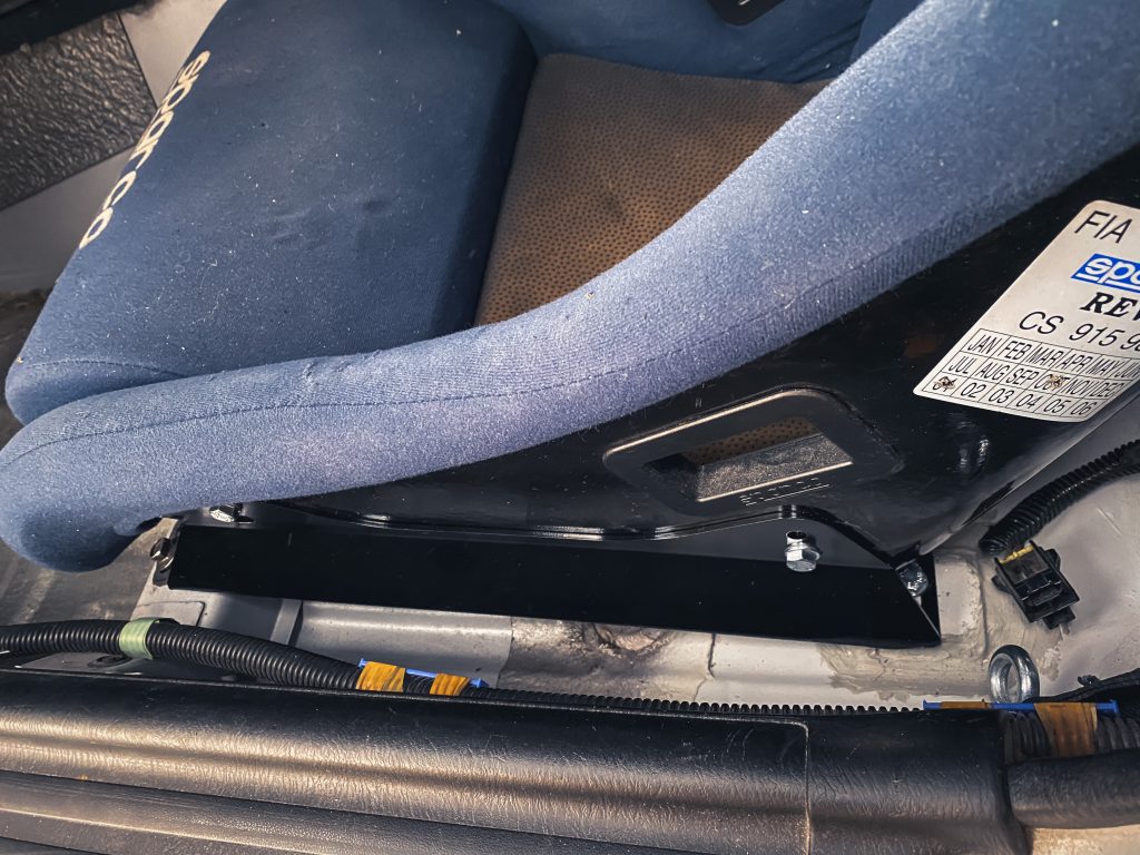
A friend of mine had the availability of a laser cutter and bender. He made the brackets for me. I welded the gap at the rear connection of the bracket and then it was time to fit the brackets. I used the brackets to cut out the tunnel hole and drill new holes in the floor for the rear connection. As the brackets have slotted holes, there was enough room to play with.
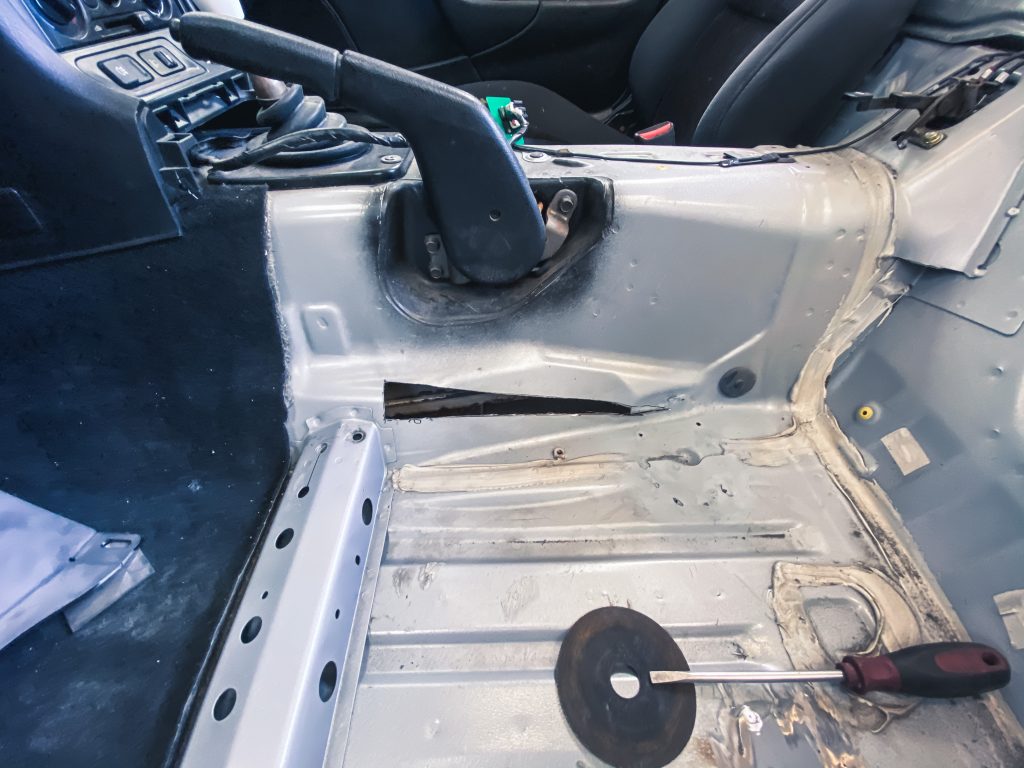
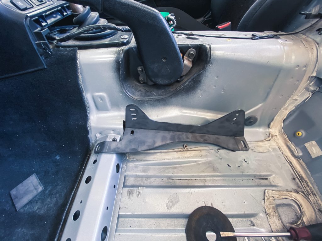
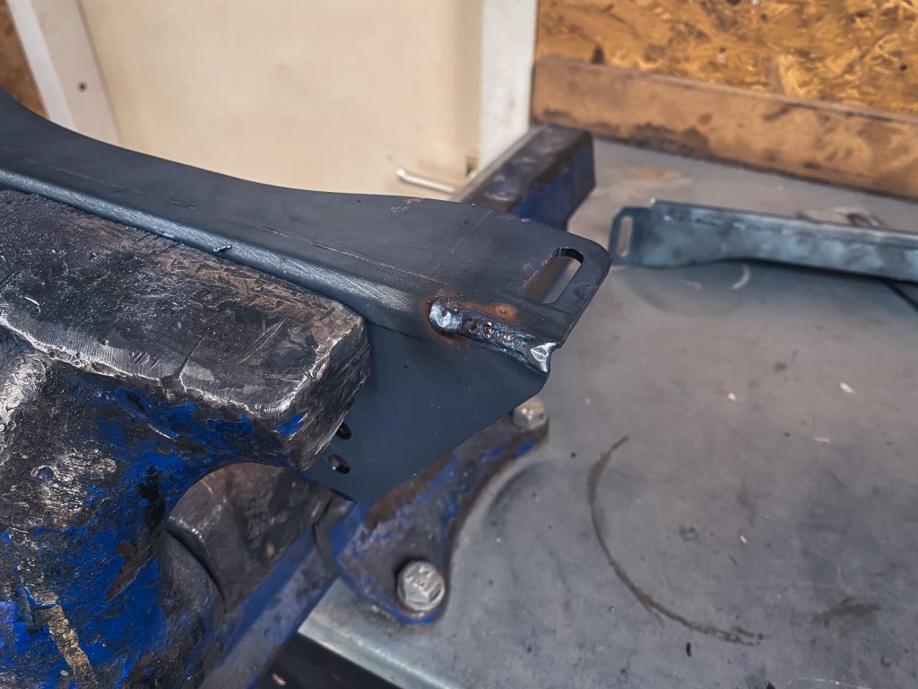
With the help of Carboard Added Design, I made a bracket to close the hole we made. It’s quite a tedious job to get the steel bracket to fit as good as possible. After all, there are so many difficult shapes in that area. However, I’m happy with the result.
After welding it got threaded with some rust protection and a layer of primer. All the welded seams got some seam sealer. Underneath the car, every seam got some seam sealer as well and over the top I added some undercoating. The interieur will be painted in a later stage when also the cage is fitted. For now it will just be protected against the elements.

It was time to mount the seat and check if I didn’t miss anything….
Frist time right?
The seat did fit, but the shoulder support was hitting the doors, even with the door cards off. With a bit more force than normal, I could get the door shut. Unfortunately, first time right doesn’t always happen. However, I could live with it – it’s a track day car after all.
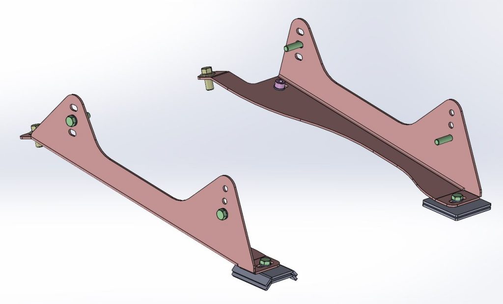
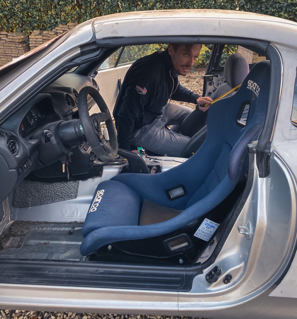
But after five times, it started to bother me to slam the door. I went on the internet to find a seat with a narrow shoulder support. Quick to find. There are tons of seats that have narrower shoulder support. I found a second hand sparco rev seat online and picked it up. Let’s first try this out with a second hand seat, before buying a new set, right?
As the seat was narrower in the waist too, I had to redesign the brackets. That’s, however, very easy when you have all the data in CAD. So after an evening of designing new brackets, the new design was ready.
Conclusion
It took some time, but I am really happy with how everything worked out. The seat position is perfect and I have a lot of other ideas for the interior. I already started working on this. However, the main focus is to fit the roof to the car and get it done to a level I can eventually bring it to the painter.
Cheers,
Jules