How did I make my own custom 3D printed cold air intake? It’s one of the many questions I still get on Instagram. I’ve written this blog post in order to answer your questions. It will tell you all about the process I went through and also give some background info on my thoughts and ideas.
To start at the beginning: why use a 3D printer? Well, I have always been fascinated by 3D printers. In my work field, we’ve used quite a lot of 3D printing, mainly for prototypes. As I wanted to learn more about 3D printing myself, I eventually bought my own 3D printer. It was a cheap, Chinese 3D printer, which I’ve modified to meet my personal needs. After a lot of fiddling, I started to produce really nice prints. It was interesting to do the whole process myself, instead of just ordering 3D prints for different prototypes. So to everyone who wants to get involved into 3D printing: I would recommend to buy your own.
The next step: what will I print?
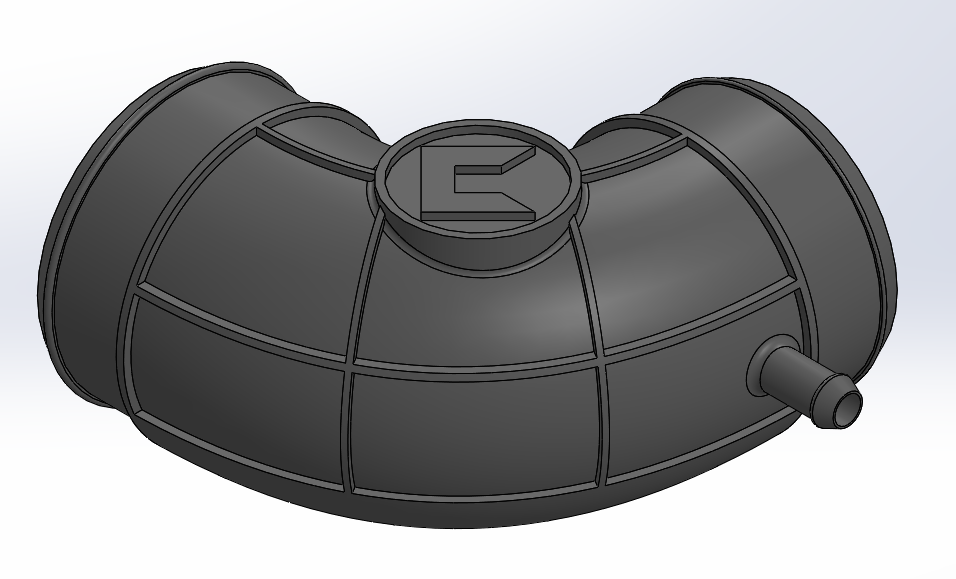
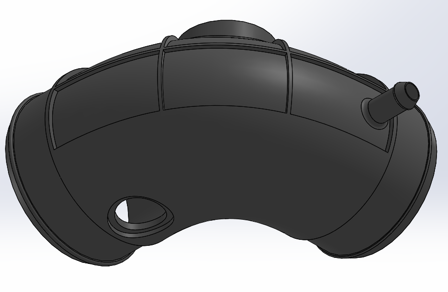
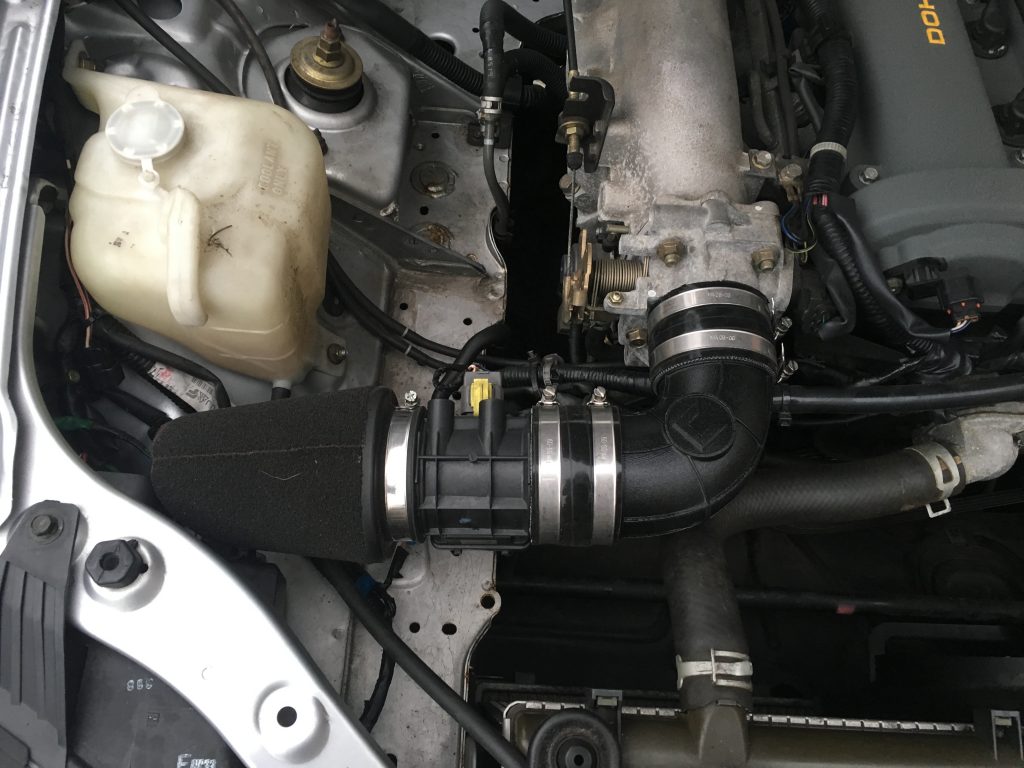
The next step: find a part to 3D print and use as a functional part within the car. As I have an mx5 and I’ve also never liked the intakes on an mx5 from a visual point of view, my choice was easy. Also, the previous owner of my car badly attached an aftermarket air filter. This sucked a lot of hot air inside the engine. Not the prettiest/best solution, so I decided to design my own intake and move it to the cold side of the engine bay. I didn’t care much about losing or gaining some performance.
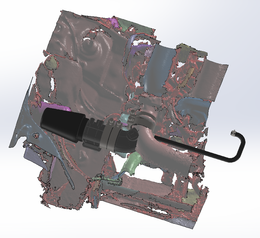
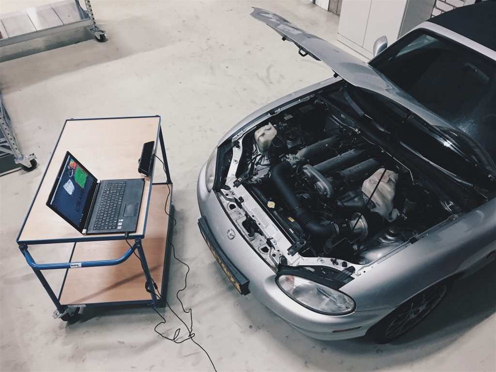
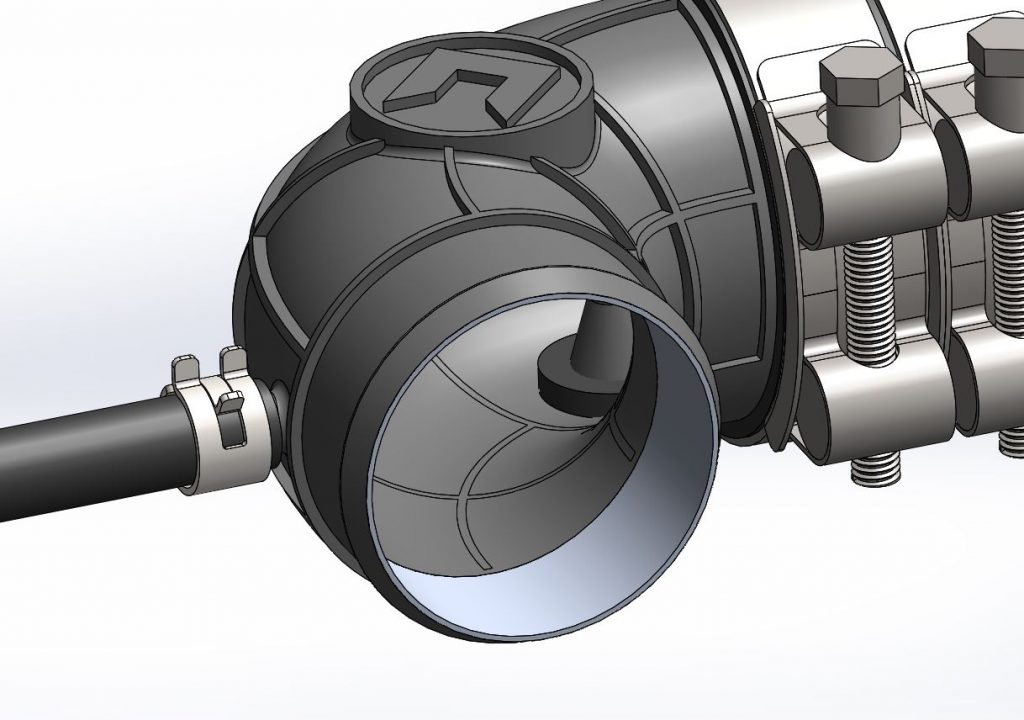
The first thing I did, was finding my old Xbox Kinekt 3D scanner to scan the area in the engine bay. These 3D scans are really rough but good enough to check the packaging. I used Geomagic to convert the scan data to surfaces and loaded it into Solidworks, where I started designing the intake. I incorporated the temperature sensor and the oil breather hose connection.
Printing the first prototype.
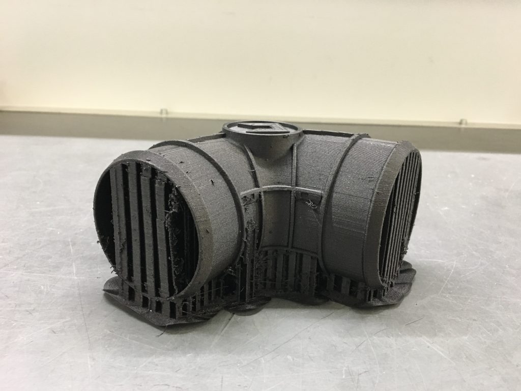
The fun part starts: I printed the first prototype. The material I used, was NylonX. This is a nylon filament with added micro-carbon fibers. At the time, it was a filament with the highest temperature resistance, which could cope with oil and petrol.
It came out quite nicely. The only thing I don’t like about FDM (Fused Deposition Modeling) printing are the supports. It takes a lot of time to remove them nicely and clean the surface. However, after a lot of cleaning and sanding the parts did look OK.
Two issues that led to a redesign.
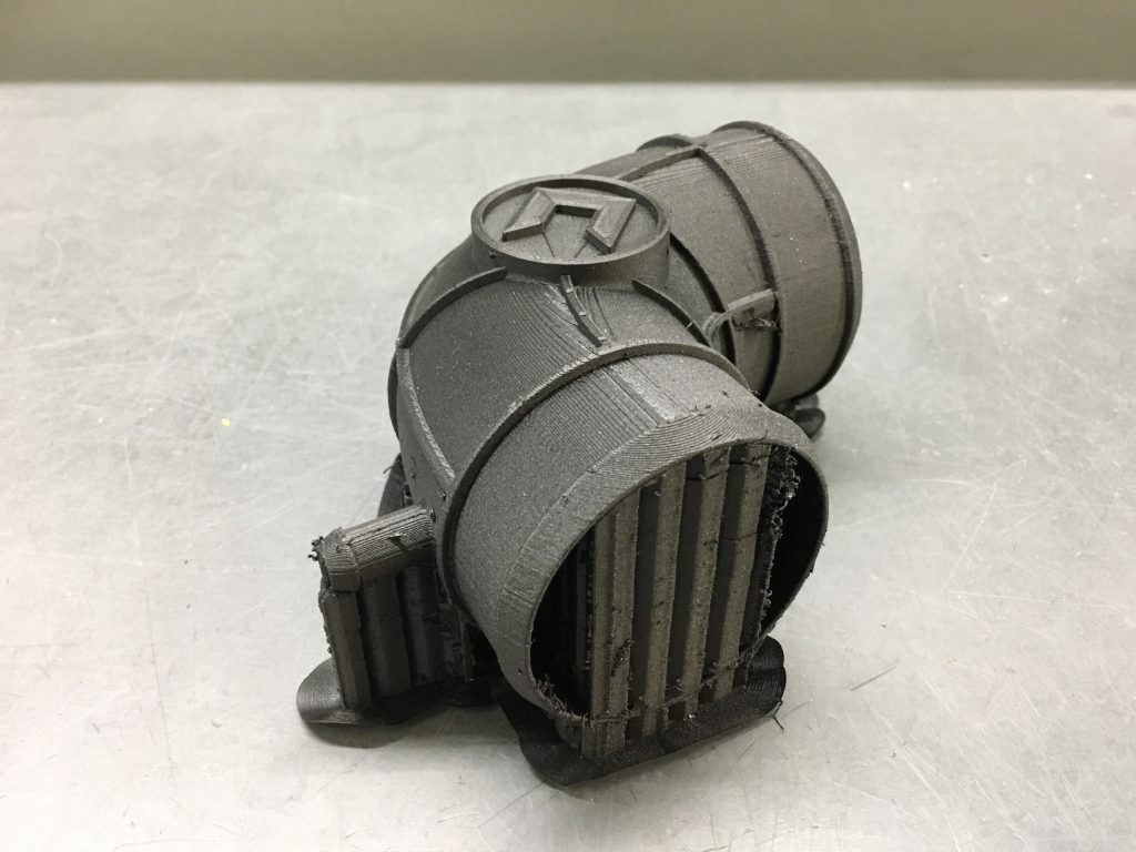
Quickly, I came to the conclusion that the intake couldn’t withstand the forces needed to clamp the tubing. I’ve redesigned the intake and made a small pocket on every end. In the small pocket, I added a piece of aluminium tubing, which I turned down in the lathe. This way, I didn’t have any problems with the clamping force. I glued the inserts with Plexus MA 310, a methacrylate glue that – as they say – will glue aluminium and nylon together. This solved the problem; clamping the tubing was no issue anymore.
The second problem I had was that I’d noticed that the intake was shrinking over time. I knew the nylon filament is known for attracting moisture. This is the reason why I always store the filament dry and closed, and bake the filament before usage. I adjusted the printing process and tried a couple of more prototypes.
The next redesign: better…. but what was wrong?
The next prototypes that came out of the printer looked great but over time, they started to shrink again. This also started to become a problem with the aluminium insert, because as you can imagine, the aluminium insert doesn’t shrink over time. This resulted in delamination of the printed intake.
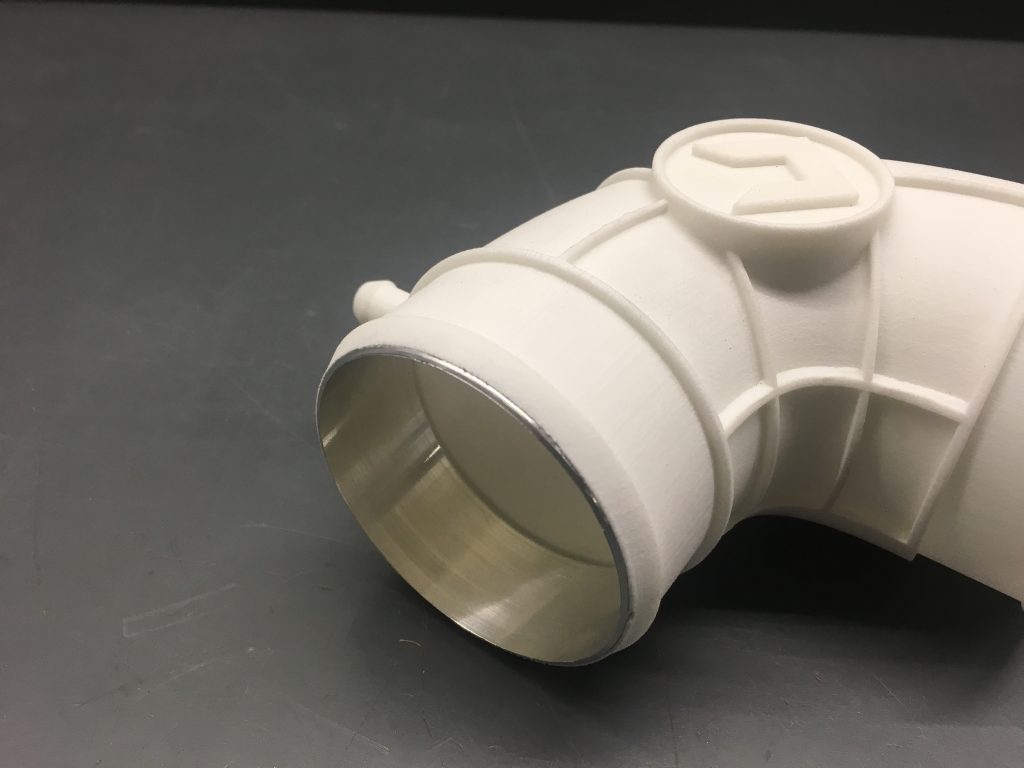
At the same time, I started to make use of SLS (selective laser sintering) printing at work. The parts that came out here were amazing, especially the surface finish element. Moreover, the work I’d put into every FDM prototype – to clean up the supports – started to get annoying.
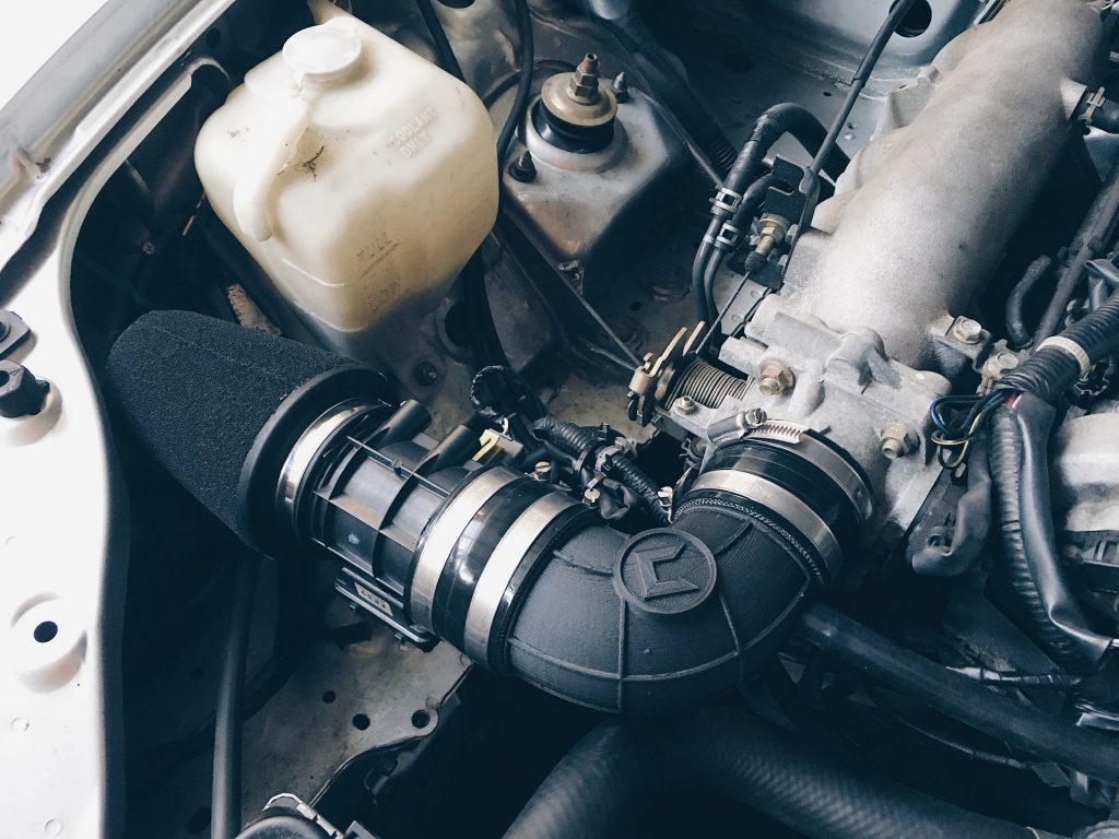
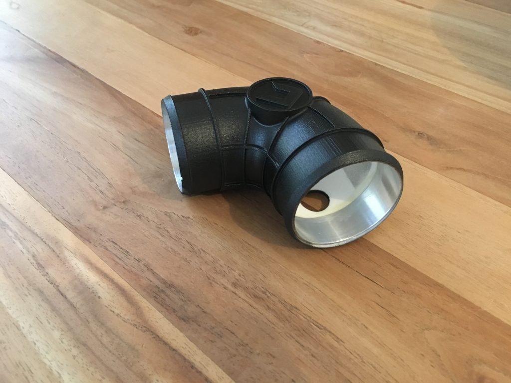
So I realized that SLS printing has some other advantages as well in comparison to FDM printing. For instance, the dimension control is a lot better and SLS printing works with a laser. This means there can’t be any moisture trapped in the 3D printed part. As a result, I ordered an SLS printed intake, glued the aluminium inserts in place, painted it black and put the intake on the car again. The results were amazing.
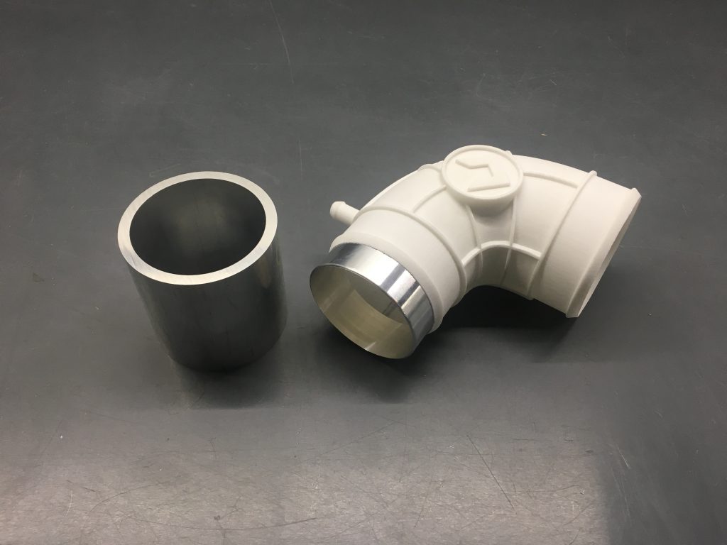
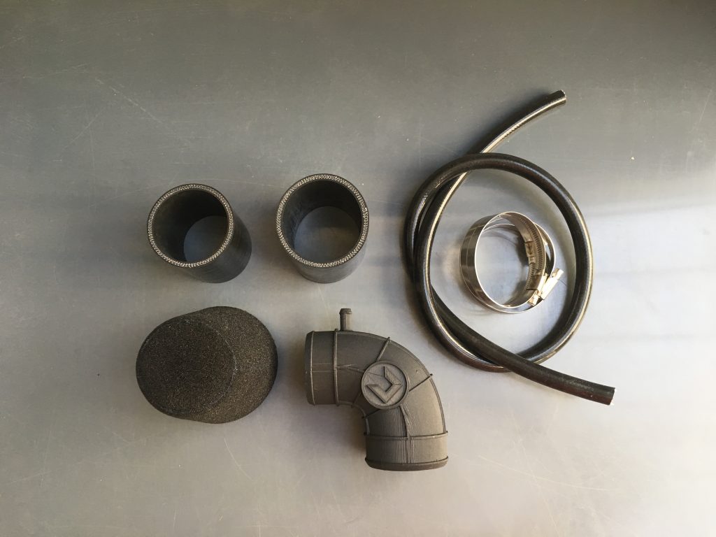
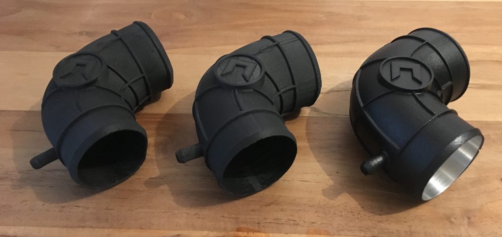
In the picture below, you’ll see two FDM prototypes (left) and the SLS printed part (right). You can clearly see the size difference due to shrinkage of the FDM printed parts over time.
The result.
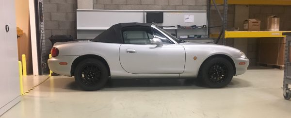
I’m really happy with the SLS printed intake. It’s on my car now for more than 2 years, without any problems: no shrinkage, no delamination and it looks a lot better than any FDM print I have ever seen.
Performance wise, I don’t feel there’s any difference compared to stock. It only sounds and looks a lot better. As I’m not the first one who moved the intake to the other side, there are some opinions. Some guys say they’ve lost some performance in the low RPM range and gained some in the high RPM range. It looks like this is the case, but maybe I was biased already by reading the experience of others. The difference is marginal.
But let’s be honest: that’s not the point of designing my own 3D printed intake. I just wanted to look if it was possible to print it myself and learn from the process. If I would gain some extra power, that’s nice. If I would lose some power, I’ve learned a lot during the process.
I hope this will clarify most of the questions about my project. Do let me know if you enjoyed reading my first real blog post and also, if you have any questions left: please send a message below or on Instagram.
Jules
One Comment
Hi I looking at making prototype for a bmw , any tips on a model to tweak , I just want to keep sure I am going in the right direction